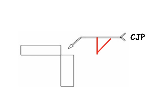
There are two types of CJP which should be understood clearly before going through the topic. JS11 Joint Design Welding Symbols Student Handout for.
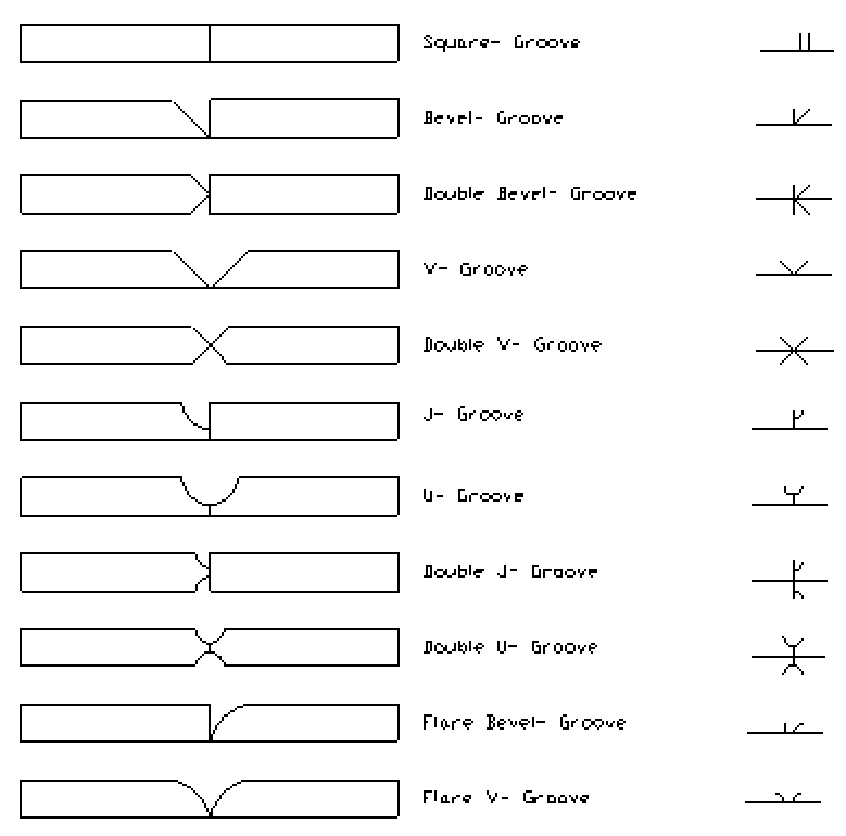
Groove Welding Symbols Interpretation Of Metal Fab Drawings
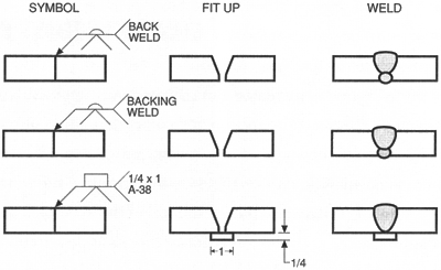
All single groove welds should be considered complete joint penetration CJP unless otherwise specified.
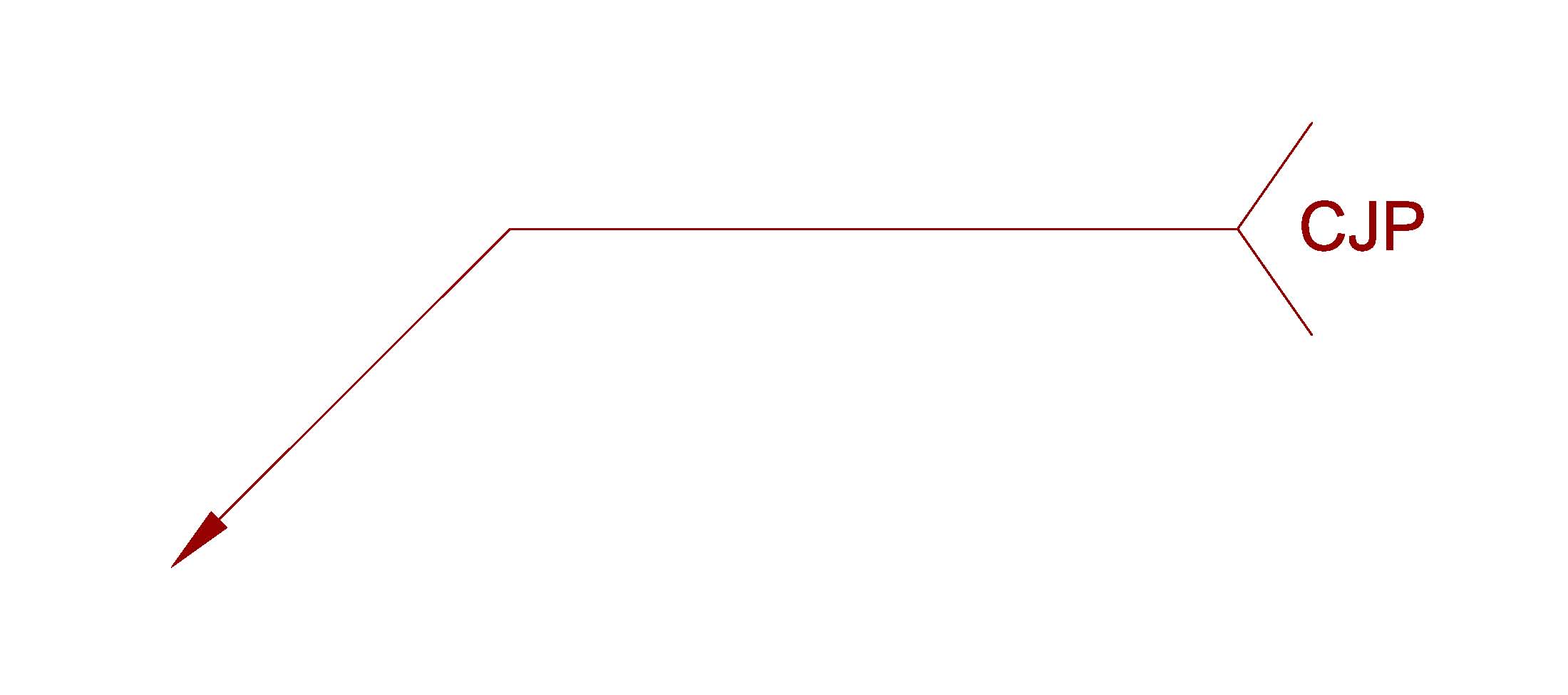
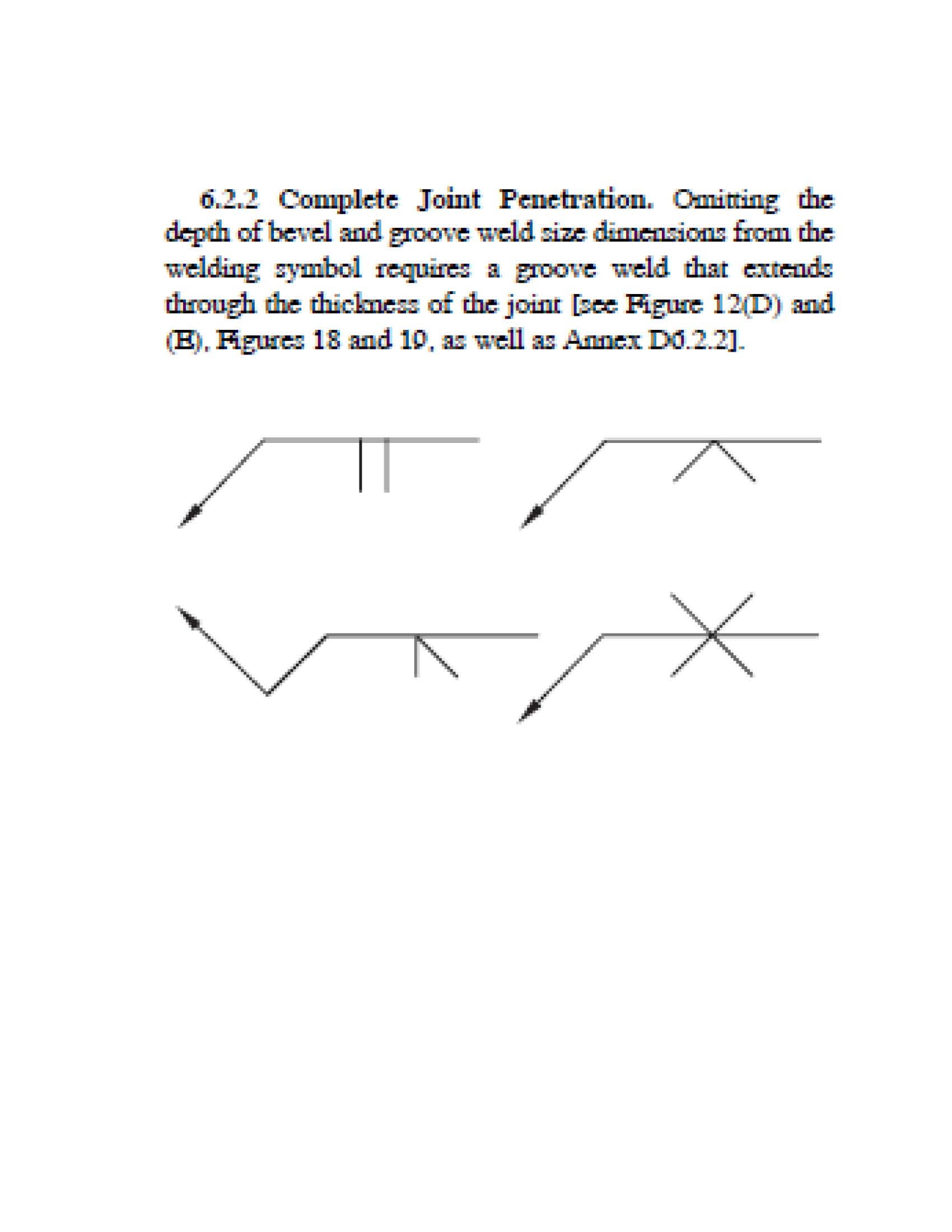
Weld symbol cjp. The welding symbol without dimensions and with CJP in the tail designates a CJP weld as follows. The welding symbol with effective weld size E1 for other side and E2 for arrow side designates a PJP weld as follows. The welding symbol without dimensions and with CJP in the tail designates a CJP weld as follow- and the symbol is shown.
As a reference you can always take a look at figure 34A of AWS A242012 Standard Symbols for Welding Brazing and Nondestructive Examinations. For example a weld symbol without a dimension and without CJP in its tail designates a weld that will. A CJP weld develops the full capacity of the connected parts where a PJP weld does not.
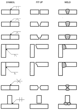
Now if this weld was intermittent the weld-all-around symbol is not used. The detail shown in. Basic Types of Welds.
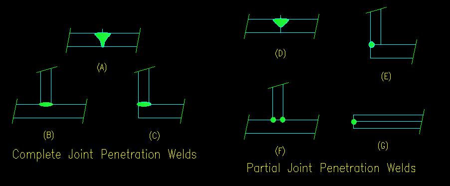
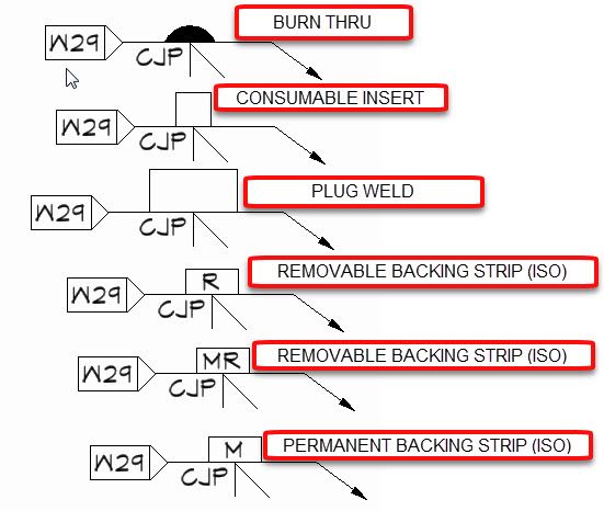
As you can see in image A below the symbol for the weld is on the underside of the reference line. The engineer need only spec-ify CJP in the tail of the weld symbol when such a weld is required as shown in Figure 3. Parts A B and C of Figure 512 illustrate CJP welds.
The weld-all-around symbol indicates that the weld continues completely around the perimeter of the joint even for circular joint members. Groove welds are considered to be either complete joint penetration CJP or partial joint penetration PJP. Just as a flag is positioned to mark a countrys site so this flag indicates.
Red Flag This Post. The scheme for the symbolic representation of welds on engineering drawings used with the third angle method of projection around the globe. Offshore structures included both CJP Type 1 and Type 2.
Fillet welds partial joint penetration welds complete joint penetration . The arrows of the symbol between the two letters indicate that a weld needs to run the full length between the two marks. In image B you can see that the symbol for the weld is on the top side of the reference line.
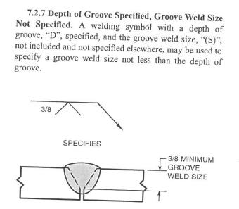
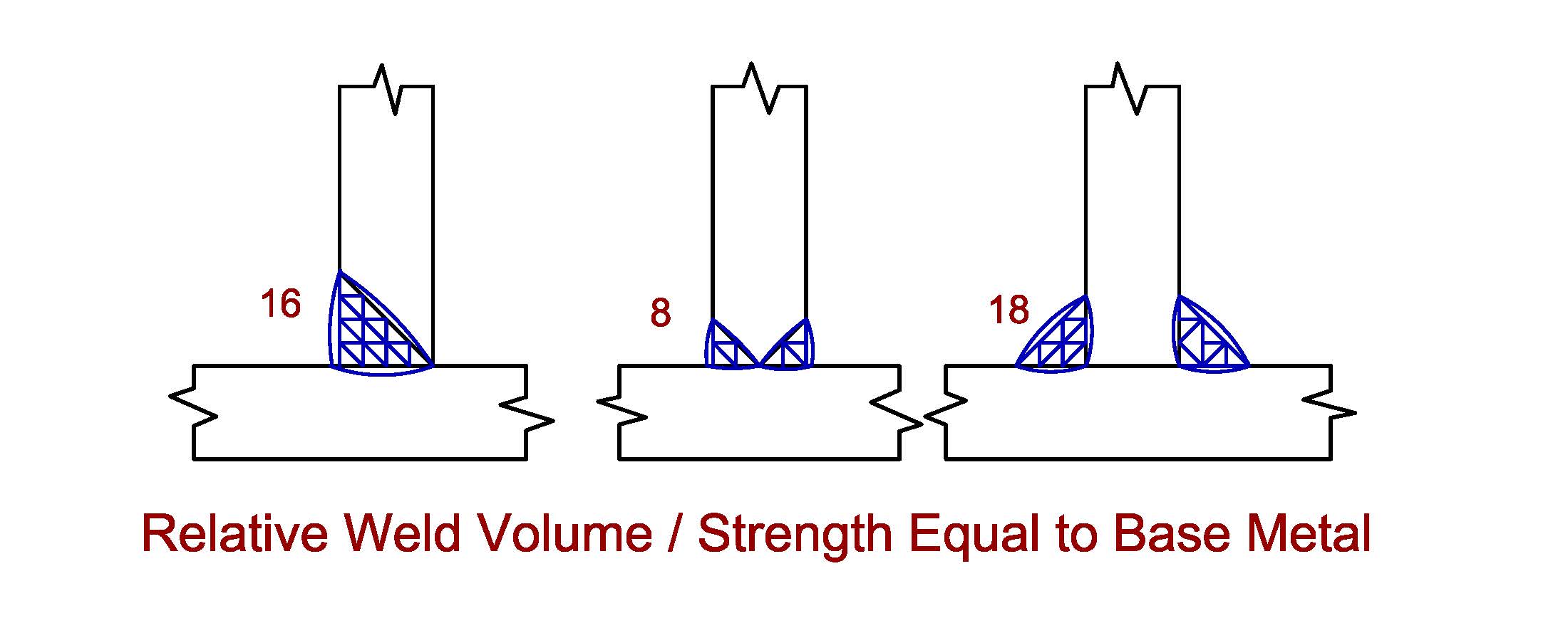
CJP welds made with appropriate filler material are stronger than the base metals that they connect so strength calculations are not necessary. For example below is a welding symbol of a single V-Groove weld on the other side. A CJP weld completely fills the gap between the two pieces.
Weld symbol is to specify the required strength of the joint required. Welding symbols are used to communicate between the designer and the welder. The welding symbol without dimensions designates a CJP weld as follows.
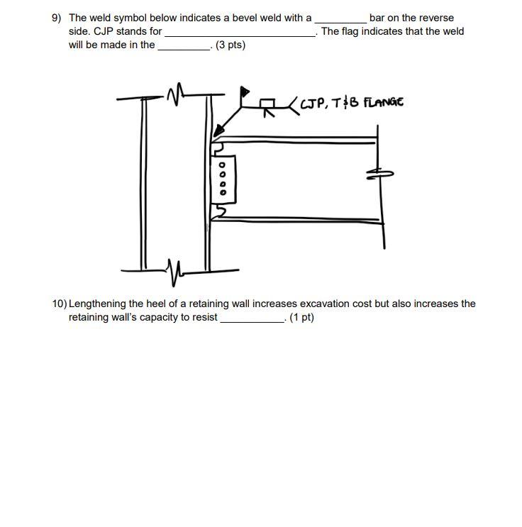
The fabricator will then design the weld to develop the strength specified as he or she sees economically fit while still abiding by the design rules of AWS D11. This symbol has a flag showing the weld needs to be done on site not in the workshop. The arrow and leader line point to the joint in question while the weld symbol tells you what type of weld to do.
When a weld is to be applied to only one side of a joint it will be called a single groove weld. Instead hatching or dimension lines would be used in order to depict the location and length of each weld. The welding symbol consists at least of a horizontal reference line has an arrow line pointing to the joint area and can have a tail with additional information for the welding process.
The welding symbol without dimension and without CJP in the tail designates a weld that will develop the adjacent base metal strength in tension and sheer. - Partial Joint Penetration PJP - Complete Joint Penetrations CJP - Flare-Bevel Groove Weld. The contractor can choose whether the weld should be a single- or double-sided weld as well as whether a V bevel U or another option is appropriate.
A joint root condition in a groove weld in which weld metal extends through the joint thickness. The effective throat of prequalified welds are given in the AWS table for that weld. If a weld is to be applied to both sides of the joint this is called a double groove weld.
The arrow and leader line point to the joint in question while the weld symbol tells you what type of weld to do. CJP complete joint penetratio n. Reasons such as off-topic duplicates flames illegal vulgar or.
If the weld symbol is below the reference line such as in symbol 1 the weld should be made on the same side as the arrow. Plug and slot welds Other types of welds include. The most frequently used weld types in the structural steel industry are.
Welding symbols are used to communicate between the designer and the welder. How much strength the PJP weld develops is based on the effective throat. If the weld symbol is below the reference line such as in symbol 1 the weld.
The drawing will show two points like an X and a Y for example between sections needing welding. Fillet Welds Groove Welds. Arc spot and seam welds Edge welds Flange welds Surfacing welds Seal welds.
Please let us know here why this post is inappropriate. When the weld symbol is on the underside of the line it is called the arrow side. The welding symbol without dimension and without CJP in the tail designates a weld that will develop the adjacent base metal strength in tension and shear A welding symbol for a PJP groove weld shall show dimensions enclosed in parentheses below El andor above E2 the reference line to.
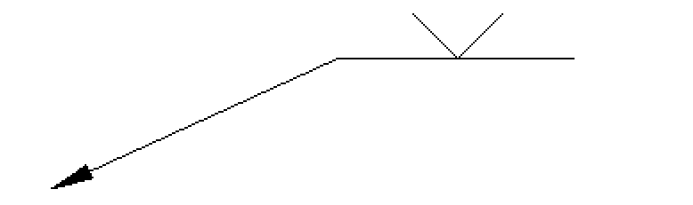
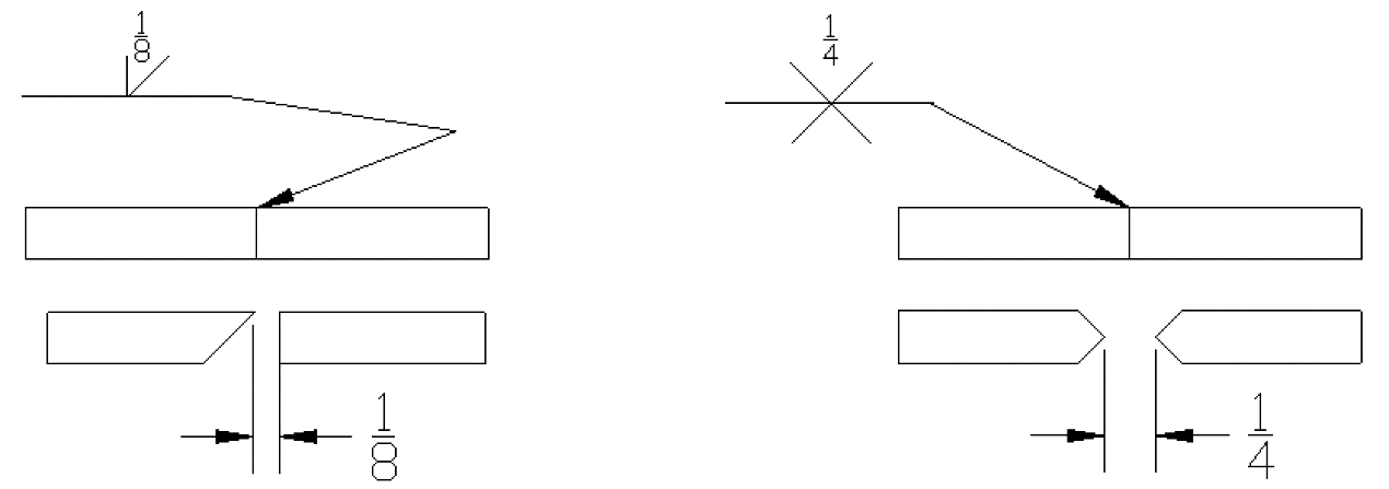
The weld symbol gives you information of the type of weld and is usually a part of the welding symbol. For example below is a welding symbol of a double bevel groove weld. Welding symbols are the integral part and the basic requirements for fabrication as they provide vital information for the joint location weld size length weld type as well as quality requirements on the fabrication or construction drawing.
There are three basic types of welds.
Weld Symbols For Handrails
Welding Intro
Weld Symbol
Is This Fp Weld Symbol
Weld Symbol Opinions
Weld Symbol Opinions

Groove Welding Symbols Interpretation Of Metal Fab Drawings
Mig Welding Outside Corner Joints

Deciphering Symbols Welding Productivity
The National Board Of Boiler And Pressure Vessel Inspectors

Welding Symbols
Deciphering Weld Symbols
Groove Welding Symbols Interpretation Of Metal Fab Drawings
The National Board Of Boiler And Pressure Vessel Inspectors
Missing Weld Symbol Autodesk Community
9 The Weld Symbol Below Indicates A Bevel Weld With Chegg Com
2
Weld Students What Are The Differences In These Groove Welds Which Are Cjp Pjp Unknown Welding

Welding Symbols

